Liquid level gauge type 708 with glass tube and metal cover
Type 708
 Applications
Level gauges type 708 are used to indicate the level of liquid in pressure vessels with a working pressure up to 10 bar (1 MPa). They can be also applied to boilers with working temperature up to 150 °C.
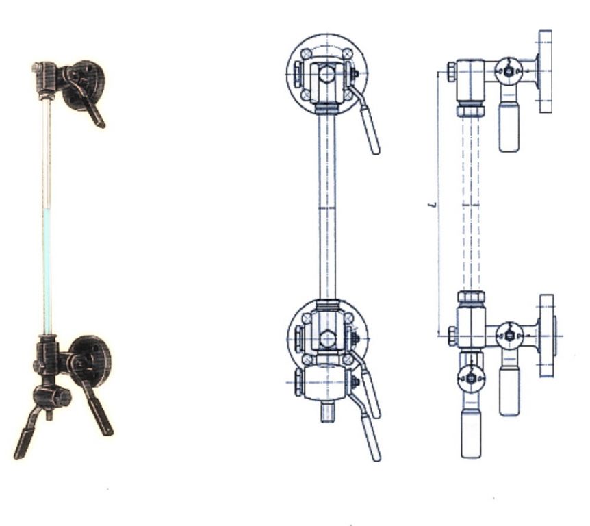
Depending on the location of handles, level gauges' heads are assembled in right or left versions.
If the order does not specify the type of version, level gauge heads are assembled in right version.
This level gauges are produced by Polish producers and are available in following versions:
- 708 - standard version
- 708CrNi - stainless steel version
Construction
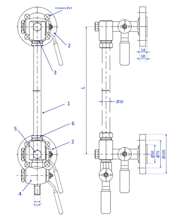
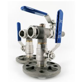
Heads consists of a glass tube (1), which is an indicating element, and two head flange (2) fitted with piston valves. Heads are connected to the gland seal (3) and drain cock (4) by using screws (5). The glass tube is sealed with a sealant gland seal pressed with a screw (6). Heads can be mounted in the implementation of the left (the handle on the left side) or right. Change of execution is obtained by loosening the screws (5) and turn of flange heads about 180 ° relative to the fastener and drain cock.
Materials
| Item | Name | Material | |
|---|---|---|---|
| 708/708Z | 708CrNi/708ZCrNi | ||
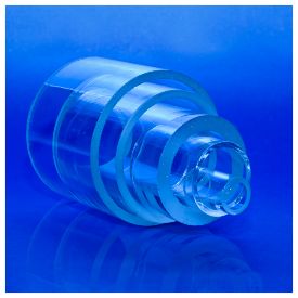
| 1 | Glass tube | Glass | Glass |
| 2 | Flange head | St4S | X6CrNiTi18-10 |
| 3 | Connector | A10X | X6CrNiTi18-10 |
| 4 | Drain cock | St4S | X6CrNiTi18-10 |
| 5 | Screw | A10X | X6CrNiTi18-10 |
| 6 | Screw plug | A10X(St3S) | X6CrNiTi18-10 |
Head mass - 5,3kg
Flanges are drilled at PN 40 as for DN20 and executed with sealing surfaces type E with spline according to PN EN 1092-1.
Level gauges can be assembled in right or left versions (depends of handle's place); as a standard are assembled in right version.
Level indicators type 708 can be supplied with tube or without tube. We can also supply additional tubes. Glass tubes to level gauges are described on page Gauge glass tubes in chapter Our offer/Technical glass/Borosilicate tubes, rods and capillaries.
The length of the tube should be calculated from the formula:
Length of tube = distance between heads L - 28 mm